2022.01.25
Thermal Management Theory--Thermal Conductivity Theories and Specific Thermal Management Methods for Thermal Design

As semiconductors and other components shrink, circuits are becoming more integrated. As a result, advanced functional electronic devices such as smartphones are becoming thinner and their structures are increasingly complex. The heat generated by these components may interfere not only with the reliability of products, but also with their safety. Heat management is absolutely required.
In order to increase the safety and reliability of electronic devices, thermal design has become essential. Thermal design estimates the amounts of heat generated from components and product beginning from the development phase, and plans for thermal management in advance. Here, we will explain basic theories of heat and specific heat management methods needed for thermal design.
Basic theories of heat
When the power is not turned on, electronic products such as PCs and smartphones are at approximately the same temperature as the surrounding environment. However, when the power is turned on and the device is operating, electrical energy is transformed into thermal energy, resulting in heating.
To understand how that heat is transmitted, it is necessary to understand basic theories such as thermal conductivity and thermal resistance.
Thermal conductivity
Heat is transmitted from hotter locations to cooler locations in accordance with the second law of thermodynamics by three methods: conduction, convection, and radiation.
- Conduction: Heat is transmitted through solid substances such as plastic or metal.
- Convection: Heat is transmitted to a gas or liquid, and is transmitted by movement of the gas or liquid.
- Radiation: Heat is transmitted by infrared and other electromagnetic radiation emitted from the heat source.
For products such as electronic devices, it is necessary to understand how heat is generated and transmitted by conduction. The materials used in various products have different thermal conductivities (a material characteristic value) , which indicates how readily the material transmits heat. The table below shows the thermal conductivity for some typical materials.
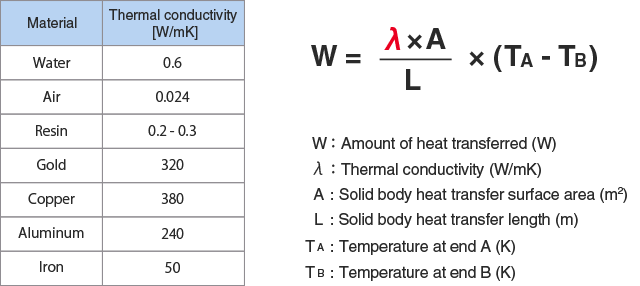
As you can see from the formula expressing the amount of heat which a material transmits by thermal conduction, materials with higher thermal conductivity transmit heat more rapidly, and they more quickly transition to thermal equilibrium.
Thermal resistance (thermal impedance)
Managing heat for when products are in use also needs to take into account material thermal resistance. Thermal resistance expresses the difficulty of heat flow, and is a comprehensive characteristic that takes into consideration a variety of conditions. It is found from the formula known as thermal Ohm's law.
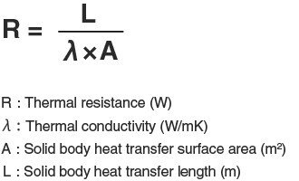
When thermal resistance is higher, it is easier for heat to build up, and it is more difficult to lower the temperature after a part is heated.
Thermal resistance is handled in the same way as Ohm's law, so it can be determined as follows based on the combination of materials.
<Series connection>
Rtotal = R1 + R2 + R3 + R4 + R5 + ・・・・ + Rn
<Parallel connection>
1/Rtotal = 1/R1 + 1/R2 + 1/R3 + 1/R4 + 1/R5 + ・・・・ + 1/Rn
Calculating the temperature of materials connected in series
Here we will calculate the thermal resistance of each material and then calculate to identify the temperature of a specific heat source.
As shown in the figure below, here we assume a material with a cross-section area of 100 mm2 located between the heat source and cooler. It is composed of aluminum, resin, and copper layers.
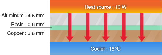
Because the materials are connected in series, the total thermal resistance of the material is the sum of the thermal resistance of each layer.
Aluminum layer thermal resistance = 0.0048 / (0.0004 × 240) = 0.050
Resin layer thermal resistance = 0.0006 / (0.0004 × 0.3) = 5.000
Copper layer thermal resistance = 0.0038 / (0.0004 × 380) = 0.025
Total thermal resistance = 0.050 + 5.000 + 0.025 = 5.075
The temperature difference ΔT between the heat source and cooler is as shown below.
ΔT = 5.075 × 10 = 50.75℃
The heat source temperature is 50.75 + 15 = 65.75℃.
In this example, we can see that the resin layer, which has the lowest thermal conductivity, interferes with heat dissipation. The following options can be used for thermal management to lower the thermal resistance of the resin layer.
- Reduce the resin layer thickness (or eliminate the resin layer).
- Change to a resin with higher thermal conductivity.
- Bypass the resin layer using a material with high thermal conductivity.
The gaps which occur in the real world as a result of physical contact between materials are also a source of thermal resistance (contact thermal resistance). When solid metals are laid on top of one another, even when they appear to be in close contact to the naked eye, on the micro level we can see that there are irregularities in the surfaces. These irregularities produce gaps. One possible way of eliminating these gaps is through the use of a TIM material.
Here we will use thermal management categories to explain the different types of specific thermal management.
Trouble caused by heat
In a product that uses electronic components such as a CPU or power device, after the power is supplied and the product starts operating, the application of a certain amount of heat can result in various issues.
Trouble related to safety
Smaller semiconductor sizes have made thinner smartphones and notebook PCs possible, and some products contain a sealed structure. With a sealed product, it is not possible to install a heat radiating fan or similar device, and the only ways for heat to escape are from the case and other surfaces.
Continual use can cause the surface to become so hot that the user cannot hold onto it, cause the internal battery to catch fire, or result in other trouble. Even at lower temperatures, prolonged contact can cause low temperature burns.
As an example, safe design guidelines have been established for smartphones and other mobile devices. In order to prevent low temperature burns, these guidelines contain mandatory standards such as the following regarding the duration of contact between materials and human bodies.
<Metal>
51°C: 1 minute
48°C: 10 minutes
43°C: 8 hours
<Glass, ceramic>
56°C: 1 minute
48°C: 10 minutes
43°C: 8 hours
<Other (resins, etc.)>
60°C: 1 minute
48°C: 10 minutes
43°C: 8 hours
Note: Mobile Equipment Safety Design Guideline P. 4
Trouble related to reliability
Using a capacitor as an example, heating causes the resin used to seal the component to undergo a chemical reaction that results in thermal decomposition. This can cause the electrolyte inside the capacitor to leak out, shortening the product lifetime.
With a component such as a power module that is composed of various materials with different coefficients of thermal expansion, stress resulting from the heat generated during continuous use can cause fatigue fracture in parts such as lead wires and soldered connections.
Trouble related to quality
The heat generated by components can also prevent full delivery of the functions listed in product specifications.
For example, in a product such as a smartphone or digital camera that is composed of many semiconductor elements, if thermal runaway occurs due to the effects of leakage current resulting from continual operation, the processing speed may be reduced or the product may be unusable until the temperature drops.
Batteries are also susceptible to the effects of temperature, and when they are used continually at high temperatures, the catalog specification for operating time may not be satisfied.
Types of thermal management
To prevent various issues that can occur due to heating in a product, thermal management must be performed to reduce the effects of heat. As indicated by the first law of thermodynamics, generated heat cannot be eliminated; it can only be moved. As a result, heat dissipation or other thermal management using one or more of the methods below is necessary.
| Thermal management | Management method | Specific examples of management |
|---|---|---|
| Increasing the heat transfer surface area | Use of heat radiating parts | Heat sink |
| Dissipating the heat in the case or other material | TIM (Thermal Interface Material) Heat spreader |
|
| Increasing thermal conductivity | Management by convection | Local cooling fan Heat pipe Vapor chamber |
| Management by radiation | Use of materials that provide high thermal radiation | |
| Lowering the device internal temperature | Ventilation | Ventilation fan Creating ventilation openings |
| Separation from the heat source | Shielding with thermal insulation Changing the component layout |
Increasing the heat transfer surface area
Heat sink
Heat sinks are a method of thermal management that have seen long use, and can be described as "heat transfer surface area expansion devices." A heat sink contains multiple fins that physically expand the surface area that dissipates generated heat.
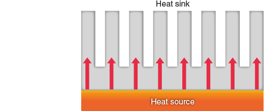
This makes it possible to efficiently move heat between solids or between a solid and the atmosphere.
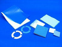
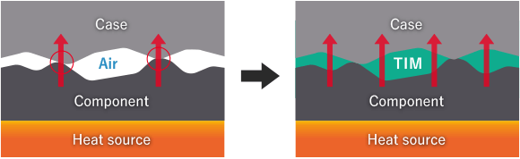
TIM (Thermal Interface Material)
Dissipating the heat generated by an electronic component into the circuit board can lower the component temperature. When the temperature drop is still not sufficient, heat is dissipated into the case or a heat sink .
Components may be connected directly to the case or allow heat to escape to the case through the circuit board. However effective heat dissipation will not be possible without lowering the contact thermal resistance at the surface where the materials contact each other.
A TIM (Thermal Interface Material) is a material that fills the minute gaps that form between the contact surfaces of the material and case, eliminating the air between them, lowering the thermal resistance, and facilitating a uniform flow of heat.
There are many types of TIM, including thermal grease and heat dissipation sheets. Specific materials and their characteristics will be explained later.
Heat spreader
A TIM is used to lower the thermal resistance at the contact surfaces between materials. A heat spreader on the other hand is a material that increases the heat transmission surface area and assists with efficient heat dissipation in the direction of the case surface.
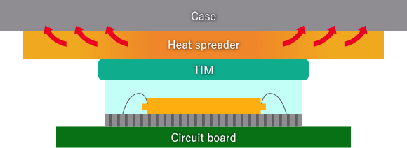
A variety of heat spreaders, such as graphite sheets or metal foil, are used depending on the application and the amount of generated heat.
Increasing thermal conductivity
Local cooling fan
This method uses a fan to create convection of heated air inside the product in order to move the heat and lower the heat level.
Use as a ventilation fan : Lowers the temperature by replacing the hot air inside the product with outside air.
Use as a cooling fan : Blows away heated air close to the heat source in order to lower the heat level.
When heating bodies are located in close proximity, relying only on natural ventilation using ventilation openings will not result in sufficient airflow and cannot produce uniform temperatures. As a result, a local cooling fan must be used to ensure the necessary airflow and achieve efficient temperature reduction.
Heat pipe
Heat pipes are cooling devices that use convection produced by a temperature difference to circulate refrigerant and move heat.
A vacuum copper pipe with high thermal conductivity contains water or other refrigerant. Heat from the heat source causes the water inside the pipe to boil, absorbing the heat of vaporization from the heat source. The vapor is then cooled at a heat dissipating part located a distance away, returning it to its liquid state. It then moves to the heat source and is heated again. This circulation produced by thermal convection can quickly achieving uniform overall temperature distributions.
Lowering the device internal temperature
Ventilation fan
Ventilation fans are installed on a case or other part, and are used to eject heated air from inside the product to the outside to achieve uniform temperatures.
Changing the component layout
It is important to review the positional relationships between components, for example by not placing a component with low heat resistance close to a part which becomes hot. When a part which generates heat is located upwind, thermal convection to the downwind side may raise the temperatures of other components. Such parts must be located on the downwind side whenever possible.
Shielding with thermal insulation
In products where changing the part layout is difficult, an effective method is heat shielding by installing vacuum thermal insulation, silica aerogel, or other thermal insulation between the heating part and other parts.
For more information about heat management, contact Taiyo Wire Cloth.
We utilize simulation technologies, measurement technologies, and other expertise in heat management to propose optimal solutions for our customers' designs. If you have concerns about heat management, please feel free to contact us.
Product Inquiries and Quotations
TIM types and characteristics
With a CPU or other device that produces a large amount of heat, efficiently dissipating the heat through the circuit board or case requires filling in the minute gaps between the contact surfaces to lower the thermal resistance. A variety of Thermal Interface Materials (TIM) types are used for this purpose.
| TIM type | Characteristics |
|---|---|
| Thermal grease |
|
| Thermally conductive sheet (gap filler) |
|
| Thermal gel |
|
| PCM (Phase-Change Materials) |
|
| Thermal tape |
|
| High thermal conductivity adhesive |
|
| Solder |
|
In addition to differences in the contact thermal resistance, TIM also differ in other ways, such as locations where they can be used and rework performance. The TIM to be used should be selected according to the application.
The purpose of a TIM is to fill the gaps between contact surfaces and reduce thermal resistance. Even when the thermal conductivity of a TIM is high, if the TIM leaks out during actual use or if an air layer remains when it is installed, it may not deliver the expected performance.
For example, when using thermal gel, material expansion and contraction occurs repeatedly due to the heat cycle which can cause pump-out which damages the material may occur, or bleeding of the oil contained in the material may result in it drying out. These issues should be evaluated and studied prior to use.
While a thermally conductive sheet provides relatively easy application work and other handling, if the correct compressive force is not applied, it will not provide the intended thermal management effects. This also must be studied during the design phase.
For information about heat management products, contact Taiyo Wire Cloth.
There are many types of TIM, and in addition to selecting a material according to the service environment, advance verification of the thermal management effects must be performed. Taiyo Wire Cloth offers a lineup of thermal management products, including gap fillers, thermal gels, and thermally conductive sheets.
For information about our thermal management products, please see the products page.